Counting Cells in the Dark: Segmentation Pipelines for Microscopy Images

Picture a mouse embryo a few days after fertilization. It starts as a single cell and divides — 2 cells, 4, 8, 16, 32, 68 on to the blastocyst stage with more than a hundred tightly packed nuclei. If you want to understand how individual cells make fate decisions during that process — which become the embryo proper, which become extra-embryonic tissue — you need to track every nucleus across time. To do that you first have to find them all, automatically, in three-dimensional fluorescence images where the signal is deliberately kept dim to avoid killing the embryo with the very light used to image it.

That was the problem behind our 2024 paper on nuclear instance segmentation for preimplantation mouse embryos[1]. It pulled me deep into deep-learning segmentation tools, benchmarking, and a realization: no single model does well at every stage of development. More recently the same fundamental challenge resurfaced in a completely different imaging context — spatial transcriptomics on tissue sections, where images are orders of magnitude larger and cells far more heterogeneous. This is the story of both.

What “instance segmentation” actually means

Three things often get conflated. Semantic segmentation answers “where are the nuclei?” as a class label per pixel — everything is either “nucleus” or “not nucleus.” Object detection draws a bounding box around each one. Instance segmentation does both: it finds every individual nucleus and produces a precise pixel-level mask for each. That last step matters for biology. You cannot measure a nucleus’s volume, shape, or fluorescence intensity without an accurate per-nucleus mask, and a nucleus is a good proxy for cell position relative to its neighbors.

For the embryo work we were doing 3D instance segmentation on volumetric stacks acquired by selective plane illumination microscopy (SPIM) — light-sheet imaging, where a thin sheet of light illuminates one plane at a time. The embryos expressed H2B-miRFP720, a near-infrared nuclear reporter the team generated for this work. Near-infrared matters: it reduces phototoxicity, and it does not overlap spectrally with the green, red, and far-red reporters biologists typically want to image alongside it. An embryo can carry up to four distinct reporters at once.

Four problems that make this hard

The challenges are baked into the biology and the microscope physics.

  • Low signal-to-noise. Light damages living embryos, so exposure is kept conservative. Foreground ends up only marginally brighter than background.
  • Voxel anisotropy. A voxel — the 3D equivalent of a pixel — is not a cube. Because the sample is imaged along a single axis, z-resolution is far worse than xy-resolution. In our data the anisotropy is roughly a factor of 10.
  • Increasingly dense packing. At the 16-cell stage the median surface-to-surface distance between neighboring nuclei is about 6.0 µm. By the 32-cell stage it is 2.9 µm; by 64 cells, 1.8 µm; past 100 cells, roughly 0.5 µm. Nuclei do not shrink proportionally, so they end up nearly touching.
  • Variable shapes and mitosis. Nuclei divide constantly. A nucleus mid-division looks nothing like a resting one.

Seven models, one benchmark

Rather than commit to one tool and hope, the team systematically evaluated seven networks on the same ground truth. That ground truth is BlastoSPIM 1.0 — more than 570 3D images with roughly 12,000 hand-annotated nuclei, spanning the 2-cell stage to past 100 cells. Each model was trained on 482 of those images and tested on held-out data.

The seven span distinct architectural philosophies:

  • Cellpose [2] — a 2D U-Net that predicts spatial gradients flowing toward each cell’s center, then clusters pixels by following those flows. Used here in 2.5D mode, processing 3D stacks slice by slice.
  • Stardist-3D [3] — represents each nucleus as a star-convex polyhedron: a set of radial distances from center to boundary. A strong fit for roughly convex objects.
  • QCANet [4] — two 3D U-Nets, one for semantic segmentation and one for nucleus-center detection, combined by marker-based watershed.
  • RDCNet [5] — 3D recurrent dilated convolutions producing embeddings that cluster into instances.
  • U3D-BCD [6] — a 3D residual U-Net jointly predicting foreground masks, instance Boundary Contours, and a signed Distance transform, combined to separate touching objects.
  • UNETR-BCD [7] — swaps the encoder for a transformer stack, keeping the BCD decoder.
  • ELEPHANT [8] — a 3D U-Net predicting nucleus center, periphery, and background probabilities.

Two metrics. The F1 score first asks, for each predicted nucleus, whether its overlap with a ground-truth nucleus clears an Intersection-over-Union threshold — IoU being overlap volume divided by union volume, with 0.5 the usual cutoff. Matches are binary. Panoptic quality is subtler: it sums the actual IoU values of matched pairs rather than counting them, then penalizes false positives and negatives. It rewards masks that are not merely detected but accurately shaped.

Stardist-3D won on F1 across stages, staying above 95% from the 8-cell stage through the 64-cell stage — well above prior state-of-the-art on comparable confocal data, especially past 32 nuclei. But the interesting result is where the models diverge, and why.

UNETR-BCD scored a panoptic quality roughly equal to Stardist-3D’s despite a clearly worse F1. The explanation: when UNETR-BCD does match a nucleus, the mask fits tightly — it just matches fewer of them. ELEPHANT ran the opposite way, posting a respectable F1 but persistently low panoptic quality, because it constrains every nucleus to an ellipsoid and real nuclei are not ellipsoids. And at very stringent IoU cutoffs Stardist-3D actually falls below UNETR-BCD, since a star-convex polyhedron with a fixed number of rays can only approximate a shape so far. Stardist-3D wins not by dominating every metric but by striking the right balance at the cutoff (≈0.5) that downstream tracking actually needs.

The failure modes were as informative as the scores. U3D-BCD, UNETR-BCD, and RDCNet tended to undersegment — merging two nuclei into one instance. Cellpose did the reverse, oversegmenting into small spurious instances or missing nuclei outright. QCANet usually predicted the right number of centroids, but its watershed post-processing split masks improperly when two centroids landed in the same contiguous region; it also isotropizes the image by degrading xy-resolution, which blurs the boundary between juxtaposed nuclei. Looking only at XY slices, several of these models seem fine. The XZ slices are where the anisotropy shows up.

When one model isn’t enough

Stardist-3D’s performance still deteriorated at the latest stages. So the team annotated 80 more images of late blastocysts — over 6,600 additional nuclear instances, a dataset called BlastoSPIM 2.0 — and trained a dedicated “late blastocyst” model on 72 of them.

It outperformed the original (“early embryo”) model on late blastocysts and underperformed it on embryos with fewer than 64 nuclei. A third model trained on both datasets landed in between — worse than either specialist in its own domain. The practical upshot is a switch: use the early model until the embryo reaches about 48 nuclei, then hand off to the late one. Even on the hardest test set, images with low foreground-background contrast where human annotators struggle, the early model held above 90% F1 through 64 cells and the late model reached ≈86% beyond that.

Around the time this work wrapped, a new class of models began reframing the problem. Cellpose-SAM [9] adapts Meta’s Segment Anything Model — a foundation model trained on enormous quantities of natural images — to cellular segmentation. Its authors used BlastoSPIM as one of their benchmarks. Out of the box it scored AP@0.5 IoU of 0.58 on our data. Fine-tuned on 300 images with ROIs, it reached 0.89. That is a large gain from a modest amount of additional annotation, and it hints at where the field is heading.

From embryos to tissue: a different kind of big

The embryo images span a few hundred micrometers. Segmenting cells in Xenium spatial transcriptomics data operates at another scale entirely. Xenium measures gene expression in situ — RNA transcripts detected directly within a tissue section, their positions recorded at subcellular resolution. To know which transcripts belong to which cell, you need cell segmentation. The images run roughly 30,000 × 30,000 pixels. Typical microscopy images are 1024 × 1024 or smaller.

Xenium stores images as pyramidal OME-TIFFs: the same image at nested zoom levels, each with its own pixel-to-micron factor. Level 0 is 0.2125 µm per pixel; each successive level halves the resolution, down to 6.8 µm at level 5. Level 3 sits closest to 1 µm per pixel, which makes it the best choice for overlaying transcript coordinates with minimal interpolation.

The segmentation challenges differ from the embryo case but are equally real. Tissue contains wildly different cell shapes — compact epithelial cells, sprawling macrophages, dendritic melanocytes — and a model tuned for round cells struggles with the outliers. More surprisingly, the nuclear channel creates a problem of its own. Nuclei are so bright relative to membrane and cytoplasmic staining that running Cellpose on all channels together causes it to segment nuclei, not cells. The nucleus comes out beautifully; the cell boundary, which is what you actually want, is swamped. The fix is counterintuitive: drop the nuclear channel. Run on membrane channels alone and cell morphology is preserved.

The tile-and-stitch pipeline

No GPU holds a 30k × 30k image, let alone runs Cellpose over it. The solution is tiling, which sounds trivial and is not.

Four stages. Load: read the OME-TIFF, parse its OME-XML metadata, extract the relevant channels and max-project to a 2D greyscale image. Tile: divide into 2048 × 2048 pixel tiles with 265 pixels of overlap on each shared edge — a step size of 1783 pixels. Segment: run Cellpose per tile, using cpsam (the SAM-based model), cyto3, or the dedicated nuclei model. Stitch: reassemble.

The overlap is essential. Without it, every cell straddling a tile boundary gets cut in half and produces garbage at the seam. But overlap creates its own problem — the same cell is segmented twice, once by each neighboring tile. We resolve this by centre-cropping: each tile contributes only its inner 1783 × 1783 region to the final canvas, discarding the 132–133 pixel margins where boundary effects are worst.

The second problem is label collisions. Cellpose numbers each segmented cell starting from 1. If tile (0,0) produces cells 1 through 250 and tile (0,1) also produces cells 1 through 250, they overwrite each other. Each tile’s labels are therefore offset by a fixed increment before being written to the global canvas, guaranteeing unique IDs across the whole image.

Compared against Xenium’s own default segmentation on two tissue regions, the pattern is consistent: cpsam on membrane-only channels wins. It reaches F1 around 0.75 and panoptic quality around 0.55, against 0.22–0.45 F1 for cyto3 on the same regions. The channel choice matters nearly as much as the model choice — cyto3’s F1 jumps from 0.22 to 0.40 on one region and from 0.45 to 0.66 on the other simply by dropping the nuclear channel. Precision stays high throughout (above 0.75); recall is the harder metric, which is what you would expect when finding every cell in dense, morphologically diverse tissue.

What comes next

The throughline across both projects is that the hardest part of computational image analysis is rarely the choice of architecture. It is the data engineering: knowing your image format, knowing which channels help and which dominate, understanding the physics of your microscope. Biology constrains the physics, physics constrains image quality, and image quality constrains what any algorithm can achieve.

What I am most curious about is how SAM-based models change the annotation economics. Both projects required enormous manual annotation — roughly 12,000 nuclei for BlastoSPIM 1.0, another 6,600 for 2.0, all hand-drawn by biologists and students. If Cellpose-SAM and its successors can hit high accuracy with 300 images instead of 500, that shifts how much expert labor each new imaging context demands. BlastoSPIM is now part of that ecosystem: someone else’s benchmark, used to evaluate a model we had no hand in building. That is a small but real contribution to the cumulative infrastructure that makes the next tool possible.

For anyone facing a similar problem — large images, heterogeneous cells, imperfect signal — the practical advice is this. Before reaching for a more sophisticated model, look hard at your data. Check what your channels are actually showing you. Inspect the z-slices, not just the xy views. And build your tiling carefully, because the seams are where things go wrong.


References

[1] Nunley H, Shao B, Denberg D, Grover P, Singh J, Avdeeva M, Joyce B, Kim-Yip R, Kohrman A, Biswas A, Watters A, Gal Z, Kickuth A, Chalifoux M, Shvartsman SY, Brown LM, Posfai E. Nuclear instance segmentation and tracking for preimplantation mouse embryos. Development. 2024;151(21):dev202817. doi:10.1242/dev.202817

[2] Stringer C, Wang T, Michaelos M, Pachitariu M. Cellpose: a generalist algorithm for cellular segmentation. Nature Methods. 2021;18:100–106. doi:10.1038/s41592-020-01018-x

[3] Weigert M, Schmidt U, Haase R, Sugawara K, Myers G. Star-convex polyhedra for 3D object detection and segmentation in microscopy. In: IEEE Winter Conference on Applications of Computer Vision (WACV). Snowmass, CO: IEEE; 2020:3655–3662. doi:10.1109/WACV45572.2020.9093435

[4] Tokuoka Y, Yamada TG, Mashiko D, Ikeda Z, Hiroi NF, Kobayashi TJ, Yamagata K, Funahashi A. 3D convolutional neural networks-based segmentation to acquire quantitative criteria of the nucleus during mouse embryogenesis. npj Systems Biology and Applications. 2020;6:32. doi:10.1038/s41540-020-00152-8

[5] Ortiz R, De Medeiros G, Peters AH, Liberali P, Rempfler M. RDCNet: instance segmentation with a minimalist recurrent residual network. In: Machine Learning in Medical Imaging (MLMI), MICCAI 2020 Workshop, Vol. 12436. Cham: Springer; 2020:434–443.

[6] Lin Z, Wei D, Petkova MD, Wu Y, Ahmed Z, K KS, Zou S, Wendt N, Boulanger-Weill J, Wang X, et al. NucMM dataset: 3D neuronal nuclei instance segmentation at sub-cubic millimeter scale. In: Medical Image Computing and Computer Assisted Intervention (MICCAI) 2021, Vol. 12901. Cham: Springer; 2021:164–174.

[7] Hatamizadeh A, Tang Y, Nath V, Yang D, Myronenko A, Landman B, Roth HR, Xu D. UNETR: Transformers for 3D medical image segmentation. In: IEEE/CVF Winter Conference on Applications of Computer Vision (WACV). Waikoloa, HI: IEEE; 2022:1748–1758. doi:10.1109/WACV51458.2022.00181

[8] Sugawara K, Çevrim C, Averof M. Tracking cell lineages in 3D by incremental deep learning. eLife. 2022;11:e69380. doi:10.7554/eLife.69380

[9] Pachitariu M, Rariden M, Stringer C. Cellpose-SAM: superhuman generalization for cellular segmentation. bioRxiv. 2025. doi:10.1101/2025.04.28.651001
Posted in Uncategorized

Finding Marx When the Words Have Changed

How do you trace the influence of an idea when the words used to express it keep changing?

That question came up in a collaboration between the Center for Digital Humanities and Professor Ed Baring in Princeton’s Department of History. The historical setting is the “Revisionism Controversy,” a debate beginning around 1897 that is often understood as foreshadowing the split between socialism and communism. One way to study that intellectual shift is to ask a deceptively simple set of questions: Who cited Marx? When did they cite him? And what, exactly, did they cite?

The corpus we were interested in was Die Neue Zeit, a large collection of German periodicals, and the source texts were Karl Marx’s Communist Manifesto and Das Kapital. If we could detect passages in Die Neue Zeit that reused language from Marx, we could begin to map how Marx’s texts were being invoked over time. But there was an immediate complication: quotations do not always look like quotations.

Sometimes a writer quotes exactly. Sometimes they abbreviate. Sometimes they paraphrase. Sometimes they translate. A method that only searches for identical strings of text will find some of the evidence, but it will miss many of the historically interesting cases.

That is the problem remarx is designed to explore: finding textual reuse across languages and large corpora, even when the reused passage is not an exact character-for-character match. The project is developed by the CDH RSE team, and the repository is available at https://github.com/Princeton-CDH/remarx.

Why Exact Matching Wasn’t Enough

The traditional approach to this kind of problem is string matching. In practical terms, that means looking for exact character sequences, repeated word patterns, character n-grams, or overlapping sets of words. These methods can work very well when the quotation is close to the original, or when the differences are small: punctuation changes, spelling variants, or a few extra words.

But for our use case, the failure modes mattered. String matching struggles when the words are reordered, when synonyms are substituted, when a passage is compressed into a shorter form, or when the reuse happens in another language. In other words, it struggles precisely when quotation becomes interpretation.

The question became: can we search for meaning rather than surface form?

This is where semantic embeddings enter the picture. An embedding is a numerical representation of text. Instead of treating a sentence as a sequence of characters, we use a pretrained neural language model to encode the sentence as a high-dimensional vector — in this case, 768 dimensions. The useful property is that sentences with similar meanings should end up near each other in that vector space, even if they use different words.

For remarx, we used paraphrase-multilingual-mpnet-base-v2, a multilingual sentence embedding model available through Sentence Transformers. The “multilingual” part matters because the same general approach can support cross-lingual reuse detection: a German sentence and a translated or related sentence in another language can still be compared by their position in embedding space. The model documentation is here: https://docs.ionos.com/cloud/ai/ai-model-hub/models/embedding-models/paraphrase-multilingual-mpnet-v2.

One helpful way to think about the process is spatially. Every sentence becomes a point. The original Marx sentences form one set of points; the sentences from Die Neue Zeit form another. If a sentence from the periodical lands close to a sentence from Marx, it becomes a candidate for textual reuse. The slides showed this with a t-SNE projection, which is a visualization technique for compressing high-dimensional vectors into two dimensions so humans can inspect the structure. The actual search still happens in the full embedding space; the visualization is just a way to make the intuition visible.

From Sentences to Verifiable Matches

The remarx pipeline has two main components. The first is the Sentence Corpus Builder. Its job is to parse source texts into sentence-level CSV files. For the German texts, we used spaCy’s de_core_news_sm model for sentence segmentation. spaCy is a natural language processing library, and sentence segmentation is the step that decides where one sentence ends and the next begins. That may sound mundane, but it is foundational: if sentence boundaries are wrong, every downstream comparison becomes noisier.

The second component is the Quote Finder. This is where the semantic search happens. The process has five main steps:

  • Embed: encode every sentence as a vector using the transformer model.
  • Index: build an approximate nearest-neighbor index using Voyager, a vector search library from Spotify.
  • Search: for each sentence in the reuse corpus, find the closest sentence from the original corpus.
  • Filter: keep only pairs above a chosen similarity threshold.
  • Consolidate: merge sequential sentence-level matches into longer multi-sentence passages.

The “nearest neighbor” idea is central. Once every sentence is represented as a vector, we can ask: which original sentence is closest to this candidate reuse sentence? Instead of a binary yes/no answer, the system produces a ranking based on similarity. That ranking is important because it lets a researcher inspect the strongest candidates first while still retaining uncertainty.

The output is designed to be checked by a human. Each detected pair includes a match_score, the reuse_text and original_text, metadata such as author, title, and page number for the reuse article, sentence indices on both sides, and a num_sentences field indicating whether the match is a single sentence or a consolidated multi-sentence passage. This was an important design decision: the tool should not behave like a black box. Every result should be traceable back to an exact position in the source text.

For development and demonstration, I used Marimo, an interactive notebook environment. Notebooks are useful here because the workflow is exploratory: tune a threshold, inspect a few results, compare scores, look at false positives, adjust, and repeat. The goal is not only to produce a final dataset, but to create a workflow where historians and RSEs can reason together about what counts as meaningful textual reuse.

The next major step is evaluation. We need metrics that capture whether the system is finding the right kinds of reuse, not just whether it finds many matches. We also want to compare remarx with existing text reuse tools such as Passim and TRACER. That comparison should help clarify where semantic embedding methods are strongest, where traditional text reuse methods still perform better, and how much human validation is needed for different research questions.

I’m also interested in extending the workflow to additional languages. The embedding model already supports 50 languages, and the sentence segmentation step is modular, so adding another language is largely a matter of plugging in the right segmentation model and testing the results carefully. That does not make multilingual reuse detection “solved,” but it does make the architecture flexible enough to ask broader questions.

What I learned from this project is that the hard part is not simply finding similarity. It is building a system where similarity can become evidence. For a historian, a high score is only the beginning of the conversation. The more useful result is a candidate passage with enough context, metadata, and traceability to decide whether it really matters.

That is where I think remarx can be most valuable: not as a machine that declares “this is a quotation,” but as a research tool that helps scholars find the places where ideas travel, change shape, and reappear.

More about the Center for Digital Humanities is available at https://cdh.princeton.edu.

Posted in Uncategorized

Making 36 GB rasters feel instant: my path to Cloud Optimized GeoTIFFs

As an RSE at Princeton, I’m often asked to help researchers move from “I have a huge GeoTIFF on disk” to “I can explore it interactively in a browser without waiting minutes for every pan and zoom.” The stakes are real: when a climate model output or satellite‑derived surface is 30–40 GB, a lab’s ability to interrogate it quickly can make or break an analysis meeting or a paper deadline. That’s where Cloud Optimized GeoTIFFs (COGs) shine.

A regular GeoTIFF is already more than an image—it embeds spatial metadata like the coordinate reference system (CRS), the projection transform, the geographic bounds, and the ground resolution, so you can lay it precisely on a map. But a standard GeoTIFF tends to be monolithic: if you want one view, most tools read a lot of bytes. A COG reorganizes the same data into small tiles (commonly 256×256 pixels), precomputes lower‑resolution overview layers in a power‑of‑two pyramid, and places the metadata at the front of the file. The result: clients can jump to exactly the tiles they need at exactly the right zoom level, and do so with simple HTTP Range requests.

From a 36 GB TIFF to a snappy COG

My starting point was a 36 GB GeoTIFF at full resolution. I tried two build paths.

  • With GDAL (the C++ geospatial workhorse), the core step was:
    gdal_translate -of COG -co OVERVIEW_RESAMPLING=BILINEAR \
      -co COMPRESS=DEFLATE -co BIGTIFF=YES \
      INPUT.tif OUTPUT.cog.tif

    On this dataset, that took about one hour. GDAL is full‑featured but typically comes via a larger conda install (~2 GB).

  • With Rasterio (a Pythonic wrapper around GDAL components) and rio‑cogeo, the equivalent was:
    rio cogeo create INPUT.tif OUTPUT.cog.tif \
      --overview-level 5 --overview-resampling bilinear \
      --cog-profile DEFLATE

    This finished in about 30 minutes, and the output shrank from 36 GB to 23 GB thanks to DEFLATE compression and overviews. Rasterio itself is a much smaller install (~25 MB), which made it convenient for quick experimentation.

Those numbers aren’t theoretical—they reflect the practical wall‑clock I saw, and they highlight the choices you’ll face: compression & predictor, number of overview levels, resampling method (I used bilinear for continuous data), and projection strategy. Each knob nudges file size, visual crispness, and read performance.

The projection fork in the road

Most web maps—Leaflet, MapLibre, and friends—speak “Mercantile” tiles, which assume EPSG:3857 (Web Mercator). You can meet them halfway in two ways:

  1. Pre‑project the raster to EPSG:3857 before (or while) building the COG. With GDAL:
    gdalwarp -t_srs EPSG:3857 -r bilinear INPUT.tif PROJECTED.tif
    # then create the COG as above; I also used -co PREDICTOR=3

    Reprojecting the 36 GB source took ~4–5 hours on our setup. The upside: the viewer can fetch tiles that are already in Web Mercator. The caveat: any resampling to 3857 changes the finest‑resolution cell values, which matters for some quantitative uses.

  2. Generate a “web‑optimized” COG with Rasterio that bakes in pyramid layers aligned for the web:
    rio cogeo create INPUT.tif OUTPUT_webopt.cog.tif \
      --web-optimized --overview-resampling bilinear \
      --cog-profile DEFLATE

    On my dataset, this took ~5–6 hours, produced a ~23 GB COG with 10 overview layers, and delivered snappy map interactions. It still involves resampling, so the same scientific caution applies at the finest scale.

Either way, the projection decision is a trade‑off: precompute for speed and convenience, or keep the source native and project on demand when precision is paramount. I often prefer dynamic reprojection for analysis workflows and precomputed 3857 for public‑facing maps.

Serving and viewing the data

Once you have a COG, the rest is delightfully boring—assuming your server supports HTTP Range requests so clients can fetch only the relevant byte ranges. Here’s the shape of a byte‑range GET in Python:

import requests
headers = {"Range": "bytes=0-65536"}
r = requests.get(url, headers=headers)

That single header is the secret sauce that makes remote, partial reads efficient. Tools like QGIS can add a raster layer from a URL to a server that honors Range; I’ve also used Leaflet in a browser, georaster + Leaflet on the client side, and a small rio‑tiler service on the server that translates x/y/z tile requests into on‑the‑fly tile renders from the COG.

For programmatic access—or to build your own tiler—rio‑tiler is a gem:

from rio_tiler.io import COGReader

with COGReader("https://example.org/data/output.cog.tif") as cog:
    img = cog.tile(x, y, z, tilesize=256, indexes=(1,))
    tile = img.data  # NumPy array (256x256)

On my 36 GB COG, this call returned a 256×256 tile in ~0.16 seconds, and it works with either a local path or a URL that supports Range reads. This is the point at which “big raster on disk” turns into “fast, precise tiles wherever your users are.” And yes, QGIS renders it nicely too.

What I learned and what’s next

The biggest “aha” was that layout beats location: simply moving a giant TIFF to the cloud isn’t enough; reorganizing it as a COG—tiling, precomputing overviews, and front‑loading metadata—unlocks performance that end users can feel. I also came to appreciate the scientific implications of reprojection: Web Mercator is great for maps, less great for certain analyses, and the choice to precompute or not should be explicit in any workflow documentation.

If you’re at Princeton and sitting on a big raster, we can help you pick options that fit your use case. For tools, I used GDAL (https://pypi.org/project/GDAL), Rasterio/rio‑cogeo (https://pypi.org/project/rio-cogeo), rio‑tiler (https://pypi.org/project/rio-tiler), QGIS (https://qgis.org), and Leaflet (https://leafletjs.com). If your server already supports Range, you’re halfway there; if not, we can stand up a small tiler to bridge the gap. My next step is packaging these patterns as a reproducible recipe with defaults (compression, overviews, and a tiler skeleton) so teams can go from raw GeoTIFF to web‑friendly COG in one command.

Posted in Uncategorized

FPGA Development for Quantum Instrumentation Control

When you’re trying to steer atoms with light, the hard part isn’t just theory—it’s timing. In our neutral-atom setup, dozens of precisely shaped laser pulses must land on micrometer-scale targets at exactly the right instants, repeatedly, while we analyze the system and adjust in real time. That’s a very different control problem than the number-crunching that GPUs excel at. It’s about determinism, latency, and orchestration of radio-frequency (RF) signals that drive acousto-optic devices modulating those lasers.

I work with the Thompson Lab at Princeton, which explores neutral-atom quantum computing with ytterbium (Yb). Yb’s nuclear-spin states encode our |0⟩ and |1⟩, and we arrange and entangle atoms using an array of trapping beams (reconfigurable optical tweezer arrays), and Rydberg-mediated interactions—then read them out with carefully timed imaging light. It’s an intricate system, with lots of different elements involving Spatial Light Modulators, Magneto-optical traps, mirrors and lenses. It also requires multiple phase-coherent RF channels feeding Acoustic Optic Modulators/Acoustic Optic Deflectors to sculpt the light in time and space, all under feedback.

Why an FPGA (and which one)?

An FPGA is a reconfigurable chip—think a sea of logic blocks (LUTs and flip-flops), on-chip memory (BRAM), DSP slices, and a fast interconnect that you “wire up” to be your custom hardware. Unlike software on a CPU/GPU, our control runs as synchronous logic with clocks, deterministic pipelines, and I/O that can wiggle pins and drive DACs with nanosecond precision. Modern devices also bundle hard processors and rich I/O into a single system-on-chip (SoC). That combination—software flexibility plus hardware determinism—is exactly what we need for neutral-atom control.

We zeroed in on the AMD Zynq UltraScale+ RFSoC family—not because it’s trendy, but because it integrates high-speed DAC/ADC with FPGA fabric and ARM cores, reducing latency and cables. The ZCU216 evaluation board, in particular, lets us aim for 16 independent RF channels with feedback, which maps well to our multi-beam AOM/AOD controls. Yes, GPUs are cheaper to prototype and easier to code, but when you compare latency, determinism, and per-channel I/O, the RFSoC wins for this use case. The cost/tooling curve is steeper than a GPU, but the payoff is reliable, real-time behavior at the edge.

The landscape we’re building in

Quantum hardware isn’t a monoculture. Superconducting, trapped-ion, and neutral-atom platforms coexist, each with different control needs. Superconducting systems prize ultra-low latency and cryogenic integration; trapped ions value connectivity but can have slower gates; neutral atoms bring long coherence and scalable arrays at the price of complex optical control. Companies across these modalities (IBM, Google, IonQ, Quantinuum, QuEra, Atom Computing) are pushing scale—IBM’s “Condor” crossed 1,121 qubits; Atom Computing reports 1,180 neutral-atom qubits—while cloud access via services like Azure Quantum makes experimentation more accessible. The takeaway for control engineers: your controller must fit the physics. For neutral atoms, that means orchestrating many RF/laser channels with strict timing, not just shuttling data.

What wasn’t working (and what we’re doing instead)

Open source firmware for RFSoC like the Quantum Instrumentation Control Kit (QICK) is impressive, but it’s tailored for superconducting qubits. In our tests, the custom embedded processor and ecosystem made development slow, and integration with other real-time stacks like ARTIQ was not straightforward. Commercial solutions exist, but they’re pricey and similarly tuned to superconducting use cases. That gap is our opportunity: build a neutral-atom-first controller on an RFSoC with mainstream tools, strong debugging, and a clean path to integrate with existing lab control.

At a high level, the project diagram I shared maps the path from a host scheduler to the FPGA’s real-time engine: deterministic pulse programs produce phase-continuous RF envelopes across many channels; fast feedback loops can tweak amplitudes based on measurements; and all of it stays locked to a shared timebase and clock tree. The RF outputs drive our AOMs/AODs, which in turn sculpt the tweezer trapping, Raman state transfer and Rydberg beams in the experiment. That’s the control loop we need, to implement fault tolerant quantum computing with neutral atoms in the lab.

How we’re building it

We’re following the classical FPGA flow: start with RTL (VHDL/Verilog/SystemVerilog) for the time-critical paths; use behavioral simulation to validate logic before synthesis; then synthesize to a netlist, place-and-route, and run static timing analysis until the design meets timing. Only then do we generate a bitstream and hit silicon. The slides included a tiny HDL example and its simulation waveform to show why sim comes first: it’s cheaper to catch an off-by-one in a simulator than on a bench at 2 a.m.

Currently we are using Vivado/xsim for simulation and synthesis with AMD Xilinx. Some open source compilers and simulators available for hardware design are Verilator, GHDL, and Python based cocotb.

The physics-to-hardware handshake

If you zoom out to the apparatus, atoms sit in an ultra-high-vacuum chamber, and we focus ~1 µm tweezers through high-NA optics. SLMs project a fixed backbone tweezer array acting as registers, and a pair of AODs shuttle the atoms between registers on the fly. The fluorescence we collect for readout is split from the trapping light and imaged on a camera. The FPGA’s job is to feed AOMs/AODs with phase-coherent RF so those optical elements can do their jobs—on time, every time—and to react to measurements quickly enough to close control loops. For background, see Henriet et al. on neutral-atom computing and an AOM primer that explains why RF agility matters.

What I’ve learned (so far) and what’s next

Two lessons stand out. First, neutral-atom control wants wide, synchronized I/O much more than heavy math throughput. That’s why RFSoC FPGAs, not GPUs, sit at the heart of this design. Second, developer experience matters: choosing mainstream tooling and simulation practice is the difference between a “cool demo” and a platform we can iterate on as experiments evolve.

Next up, I’m hardening the RF channel pipeline—phase-continuous DDS blocks, envelope shaping with precise start/stop semantics, and a low-latency feedback path tied to the measurement chain. In parallel, I’m prototyping the host interface that can speak to (or coexist with) ARTIQ and the rest of the lab stack. As we polish the core, I’ll share a public repo and documentation; in the meantime, the Thompson Lab and Princeton Quantum Initiative pages are good context on why we’re investing here, and the Princeton Engineering write-up on illuminating error processes in neutral-atom systems motivates the kind of precise control this effort supports.

Thompson Lab
High-fidelity gates and mid-circuit erasure conversion in an atomic qubit

Posted in Uncategorized

Building a Finite Difference Seismic Solver with Rust + WebGPU

The project (icui.github.io/seiswg) I’ll talk about here started as an attempt to answer a simple question: can we build a serious finite difference seismic solver that is portable across GPUs, and even runnable in a browser, without maintaining multiple codebases?

Building a seismic solver that runs everywhere

Seismic wave simulation sits at an uncomfortable intersection of scientific ambition and hardware reality. On one hand, finite difference solvers are conceptually simple and great for prototyping, benchmarking, and teaching. On the other, once you care about scale, performance, or inversion workflows, you quickly become dependent on GPU acceleration—and that usually means CUDA, and that usually means NVIDIA.

That tradeoff was fine when the audience was limited to a specific cluster. It became much harder to justify when people wanted to run the same models on Apple Silicon laptops, shared institutional resources, or even inside a browser for teaching and experimentation. That tension is what pushed me to rethink how we structure GPU-based seismic solvers in the first place.

From Python and CUDA to something more portable

The starting point was Seispie, a finite difference seismic solver written in Python with GPU acceleration via numba-cuda. It supports forward simulation, adjoint runs, and full waveform inversion. Functionally, it overlaps with packages like SPECFEM++, but with a more straightforward and less mathematically heavy implementation.

That simplicity made Seispie useful in several contexts:

  • benchmarking new physical models (like Cosserat media),
  • prototyping new ideas quickly,
  • and teaching wave propagation without overwhelming students with framework complexity.

But there was a hard limitation: numba-cuda ties you to NVIDIA GPUs. If your hardware doesn’t support CUDA, the code simply doesn’t run.

I looked at other portability options that are common in HPC—Kokkos and SYCL were both on the table—but neither quite fit what I wanted. What surprised me was that the most compelling alternative didn’t come from the traditional HPC ecosystem at all: it came from the web.

Why WebGPU—and why Rust?

WebGPU is a relatively new standard that provides low-level access to native GPU APIs like Vulkan, Metal, and DirectX 12 through a unified interface. Despite the name, it’s not limited to graphics or browsers. It explicitly supports general-purpose GPU compute.

Three properties made it attractive for this project:

  • it runs on most modern GPUs, including Apple Silicon and mobile hardware,
  • it doesn’t require users to install vendor-specific SDKs,
  • and it is designed to work both in browsers and in native applications.

WebGPU kernels are written in WGSL (WebGPU Shading Language), while host code can be written in several languages. Rust stood out—not only because I wanted to start a serious Rust project, but because Rust can target both native binaries and WebAssembly (WASM) with the same codebase.

That led to a design goal that shaped everything else: the same solver should run as a standalone executable on a cluster and as a static webpage in a browser.

How the architecture changed

Originally, the workflow looked like this: Python orchestrates everything, finite difference kernels are written in numba-cuda, and CUDA directly talks to the GPU.

In the new design, there are two closely related workflows.

For a standalone executable, Rust handles the main workflow, WGSL implements the finite difference kernels, and WebGPU implementation (wgpu) maps those kernels to Vulkan, Metal, or DX12 depending on the platform.

For a static webpage, the picture expands. Rust still owns the workflow logic, but it compiles to WebAssembly. JavaScript provides the Web APIs. WebGPU implementation (browser engine) handles GPU execution, and browser storage mechanisms (like IndexedDB) stand in for a traditional filesystem.

One important discovery here was how much the WebGPU implementations like wgpu and browser engines do for you. They automatically map WebGPU calls to the correct native backend on each platform. That abstraction is solid and largely invisible once things are set up.

What they do not handle are the browser-specific pieces: fetching files, persisting data, or coordinating with JavaScript. Those still require explicit glue code, and file I/O in particular opens up questions about newer browser features like OPFS that could merit a project of their own.

Writing GPU kernels in WGSL

A big unknown going in was whether WGSL would be usable for real scientific compute kernels. To test that, I asked Claude to translate existing finite difference code directly.

In numba-cuda, a backward finite difference operator and a stress divergence kernel are compact and expressive, with Python syntax and implicit device context.

// Backward differences (centred on k):
//   ∂f/∂x ≈ [9(f_i - f_{i-1}) - (f_{i+1} - f_{i-2})] / (8 dx)
@cuda.jit(device=True)
def diff_x(v, i, k, dx, nx, nz):
    if i >= 2 and i < nx - 2:
        return 9 * (v[k] - v[k-nz]) / (8 * dx) - (v[k+nz] - v[k-2*nz]) / (24 * dx)
    else:
        return 0
/// ∇·σ^SH → DSY    (divergence of SH stress)
@cuda.jit
def div_sy(dsy, sxy, szy, dx, dz, nx, nz):
    k, i, j = idxij(nz)
    if k < dsy.size:
        dsy[k] = diff_x(sxy, i, k, dx, nx, nz) + diff_z(szy, j, k, dz, nx, nz)

In WGSL, the same math is there, but everything is more explicit: types, buffer access, indexing logic, and execution parameters all have to be spelled out. The result is undeniably more verbose, but also very transparent. Once written, the WGSL kernels compiled and ran consistently across platforms. And the core GPU kernels are not too different from the CUDA kernels.

// Backward differences (centred on k):
//   ∂f/∂x ≈ [9(f_i - f_{i-1}) - (f_{i+1} - f_{i-2})] / (8 dx)
fn diff_x(fid: u32, i: u32, k: u32) -> f32 {
    if i < 2u || i >= params.nx - 2u { return 0.0; }
    let nz = params.nz;
    let dx = params.dx;
    return ( 9.0 * (gf(fid, k) - gf(fid, k - nz))
           - (gf(fid, k + nz) - gf(fid, k - 2u * nz)) ) / (8.0 * dx);
}
/// ∇·σ^SH → DSY    (divergence of SH stress)
@compute @workgroup_size(64)
fn div_sy(@builtin(global_invocation_id) gid: vec3) {
    let k  = gid.x;
    if k >= params.npt { return; }
    let ij = ij_from(k);
    sf(F_DSY, k, diff_x(F_SXY, ij.x, k) + diff_z(F_SZY, ij.y, k));
}

Calling those kernels from Rust via wgpu involves a clear but structured sequence: allocate GPU buffers, bind them to the shader, create a compute pipeline, dispatch workgroups, and submit commands to the queue. The ceremony is heavier than in CUDA, but it’s predictable—and crucially, it’s the same whether you’re running in a browser or on a cluster.

What I learned

By the end of this experiment, a few things were clear to me.

WebGPU is real. It’s not just a graphics API in disguise; it’s a broadly supported, forward-looking GPU compute standard.

Rust pairs well with it. Having one host language and one kernel language span native executables and browser deployments is surprisingly powerful.

There are still rough edges. Web APIs and browser file systems don’t disappear just because your compute core is portable. And WGSL demands more boilerplate than CUDA or numba.

But overall, this felt like a glimpse of a different future for research software—one where portability isn’t an afterthought, and where the same scientific code can live in a phone, a cluster job, and a webpage without being rewritten three times.

Acknowledgements

The initial draft of this blog post was generated by Microsoft Copilot by Abhishek Biswas and Tai Sakuma.

SPECFEM++ — A Modern, Unified Rewrite of a Seismology Workhorse

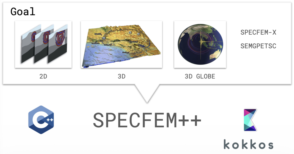
SPECFEM has been a cornerstone of computational seismology for over two decades. The Fortran-based software suite is used for seismic wave propagation simulations and adjoint tomography, accumulating thousands of citations per year across a broad user base. But the original codebase grew across three separate repositories (2D, 3D, and 3D Globe) with substantial redundancy and architecture-specific GPU kernels, meaning new features rarely made it to all variants.

SPECFEM++ is the solution: a ground-up rewrite in C++ using Kokkos for performance portability across CPUs, NVIDIA GPUs (CUDA), and AMD GPUs (HIP) — all from a single codebase.

Expanded Physics

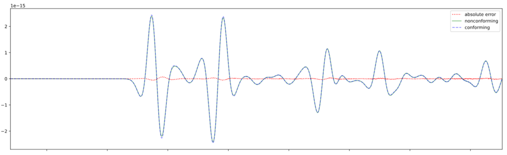
One of the primary goals of SPECFEM++ is to make adding new physics straightforward. The solver now supports elastic P-SV and SH waves, anisotropic media, poroelastic domains, and Cosserat media (which adds rotational degrees of freedom alongside displacement). Most significantly, 3D elastic isotropic simulation is now fully supported, with end-to-end integration tests confirming sample-by-sample agreement with SPECFEM3D Cartesian.

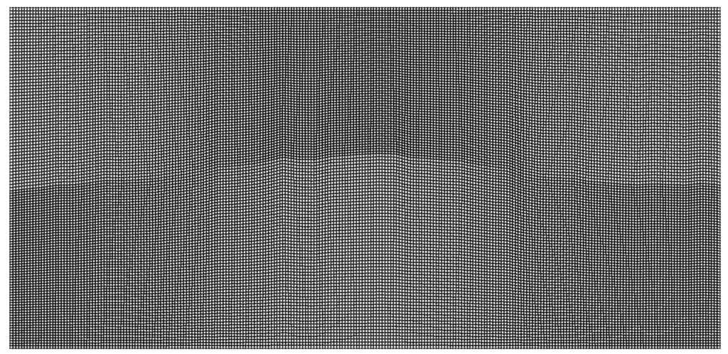
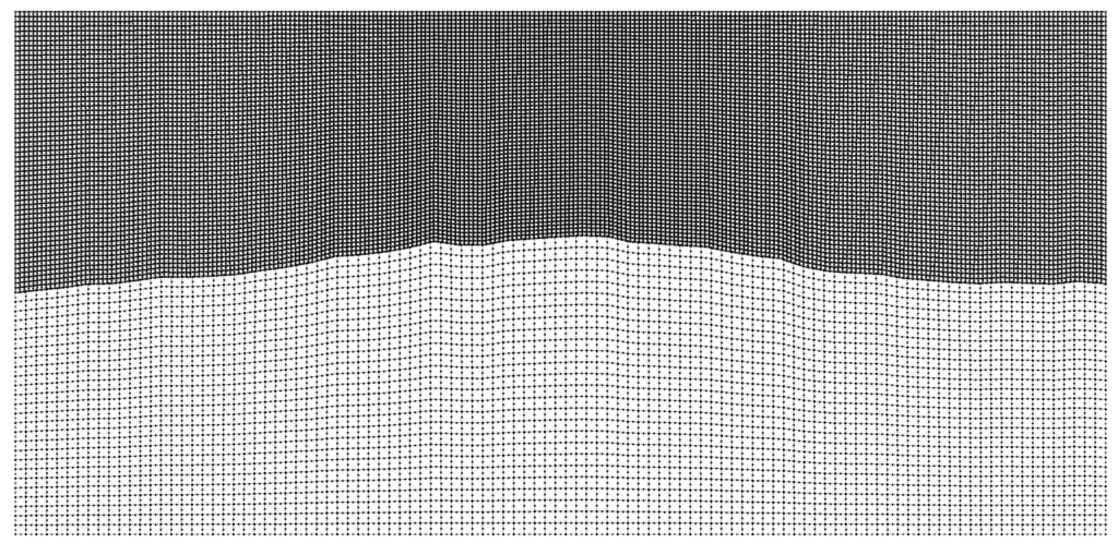
For problems with large contrasts in physical properties, non-conforming mesh support via a Discontinuous Galerkin approach allows different element sizes on either side of an interface. This enables the code to choose larger timesteps and drastically improve performance.

Associated Non-conforming simulation.
The conforming simulation is part of Pipatprathanporn et al., 2024 (DOI). Credit: Kentaro G. Hanson (G3, PACM).
Seismograms for conforming and nonconforming DG simulation as well as associated error. Credit: Kentaro G. Hanson (G3, PACM).

Performance on Par with — and Beyond — SPECFEM2D

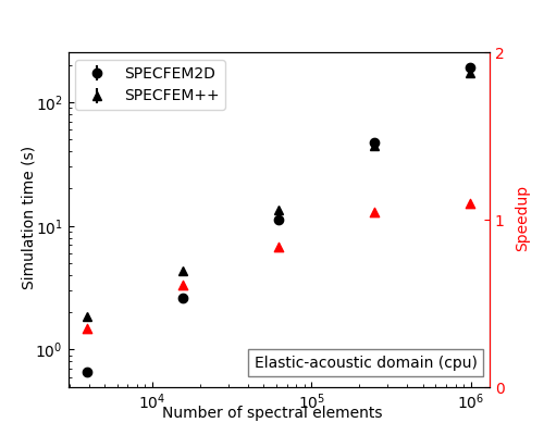
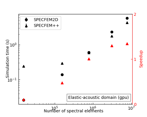
After memory layout optimizations, SPECFEM++ now matches SPECFEM2D on CPU for elastic and acoustic problems. On GPU, it pulls ahead: for large elastic-acoustic domains (10M+ spectral elements), SPECFEM++ achieves up to 2× speedup over SPECFEM2D.

Real-World Benchmarks: Marmousi and Cosserat

Two showcases stand out. The Marmousi model cookbook runs wave propagation on a high-resolution CUBIT mesh derived from a classic seismic benchmark, and is a great stress test of the GPU backend. The Cosserat media simulation illustrates the rotational wavefield alongside displacement — something not possible in the original SPECFEM.

Wave propagation due to an isotropic, explosive source in the complex Marmousi model. Water (acoustic) layer on top and a complex, solid layer below with Stacey Boundary conditions.
Wave propagation in a homogeneous Cosserat medium with Stacey boundary conditions on all sides. Left: Magnitude of the displacement component. Right: Rotational (spin) component. Credit: Max Chien (Junior, PACM).

Tooling and Documentation

Nightly benchmarks run automatically via Jenkins on Intel Gold CPUs and NVIDIA H100 GPUs, with results on a live review dashboard. The API documentation now includes the actual implemented equations, and cookbooks cover everything from basic homogeneous media to non-conforming fluid-solid interfaces.

What’s Next

Active development is focused on MPI support, attenuation, and acoustic-elastic coupling — the remaining pieces needed for large-scale parallel 3D production runs.

SPECFEM++ is a community project with monthly developer meetings (first
Wednesday of each month, 12:00 PM Eastern sign up here). Documentation is at specfem2d-kokkos.readthedocs.io and the code is on GitHub.


Acknowledgements: The initial draft for this post was generated by Anthropic’s Claude Sonnet 4.6 using presentation slides and github release notes.

Taming memory—and making room for more physics

As a Postdoctoral Research Associate working in computing for high‑energy physics (HEP), I spend a large amount of time thinking about reducing RAM usage, because it’s the most precious resource we usually have on our computing clusters. Decreasing memory usage by 20% effectively means we can run 20% more jobs in parallel and that’s powerful when analyzing billions of detector events.

In a recent 20‑minute RSE group talk, I shared two threads from our work: first, how memory fragmentation in Python‑driven HEP workflows can look like a memory leak; and second, how delivering only the arrays we need—when we need them—lets us analyze more events without buying more RAM.

1) Memory fragmentation isn’t a leak—but it sure looks like one

When a program needs memory, it asks the OS via syscalls like sbrk/mmap. Doing that constantly is expensive, so allocators grab larger chunks (“arenas”) and parcel them out. Over time, those arenas can get fragmented. There’s internal fragmentation (you asked for 15 B, you get 16 B—typically multiples of 4) and external fragmentation (freed holes can’t be reused by differently sized objects). The oversimplified cartoon version: allocate A/B/C in a 12 kB arena, free B (you “waste” 4 kB), then allocate a larger D and you end up needing a second arena—24 kB in use even though your live data could fit in 16 kB.

Our trigger was Uproot reading of ROOT TTrees—lots of differently sized NumPy arrays interleaved with many tiny Python objects. Iterating a CMS NanoAOD open‑data file with tree.iterate(step_size="20 MB") on macOS showed a steadily increasing resident set size (RSS). That graph screams “leak,” but the culprit is fragmentation. Swapping the default allocator for mimalloc stabilized RSS and cut peak memory roughly in half on macOS. Links to prior observations are here: Uproot 5 discussion and a coffea issue for similar symptoms.

The twist: this behavior is environment‑dependent. On Linux (e.g. using the coffea‑casa computing infrastructure), fragmentation was smaller to begin with and mimalloc actually made things slightly worse. Add Python’s garbage collector to the mix—collection timing is stochastic—and you have a debugging problem that’s hard to understand and easy to misdiagnose as a true leak. A forward‑looking note: the new RNTuple format is expected to behave more robustly, and is ready to be used with Uproot.

2) Optimized array delivery: only keep in RAM what an Awkward operation needs

HEP event trees are wide: >1000 columns is normal, while a typical analysis uses on the order of ~50. Last year I worked on VirtualArrays in Awkward Array—lazy columns that load only when touched—which already moved us from O(10) GB down to O(1) GB for many analyses. But we can go further by controlling not just which arrays are available, but when they’re resident in memory for a given operation.

We implemented three array delivery options, each exposing a Python MutableMapping interface so analyses can swap strategies without refactoring:

BufferCache — basically a dictionary: arrays materialize lazily and stick around. Think of this as “plain” VirtualArrays.

CompressedBufferCache — arrays are always stored compressed in RAM (blosc + ZSTD, clevel=1, bit‑shuffling) and decompressed on access.

HDF5BufferCache — arrays live on disk in an HDF5 file near the CPU; __getitem__ reads them on demand, after usage they’re dropped again from RAM (they’re still on disk). On my local Apple SSD I measured ~10.73 GB/s reads and ~2.67 GB/s writes for this benchmark.

For a realistic micro‑analysis on CMS public data (~1M events), and with mimalloc enabled to neutralize fragmentation (that we discussed earlier in this post), we saw:

  • BufferCache: peak RSS 1.51 GB, runtime 13.48 s.
  • CompressedBufferCache: peak RSS 1.01 GB, runtime 14.10 s.
  • HDF5BufferCache: peak RSS 0.73 GB, runtime 13.34 s.

That last result is the punchline: by keeping arrays off RAM until the moment of use, peak memory fell to ~730 MB with essentially no runtime penalty relative to the in‑memory baseline. Since SSDs are dramatically cheaper than DRAM in our clusters, this is a practical way to “buy” effective memory: more events fit in a single job, which means bigger Awkward Arrays and thus greater SIMD benefits of our kernels.

Put together with the earlier story, the picture looks like this:

  • Eager materialization of all columns: >10 GB.
  • Lazy VirtualArrays (status quo): ~1.5 GB (≈10× reduction).
  • Lazy on‑disk VirtualArrays (e.g. with HDF5): ~0.73 GB (another ~2×).

What I’m taking forward

Two lessons stuck with me. First, in certain software scenarios climbing RSS isn’t necessarily because of a “leak”: inspect allocator behavior and OS differences; try an alternative allocator like mimalloc and verify on the platform you’ll run at scale. Second, lazy data access and using data only when it’s needed is a powerful pattern. By aligning array lifetimes with actual operations—and being able to store them compressed in-memory or on disk (e.g. SSD)—we enable processing more collision events in parallel without changing analysis code semantics. If you’re working with Uproot, Awkward Array, or coffea and want to try the cache strategies, I’m happy to compare notes and share code.

Links & attributions

Posted in Uncategorized

Launching an Interactive Hydrology Dashboard on HPC with Open OnDemand

As a Research Software Engineer, I work with Professor Reed Maxwell’s group, helping scientists better understand how water moves through the environment. Our lab studies computational hydrology, which means we use mathematical models to simulate how groundwater and surface water flow across landscapes. These simulations help researchers explore questions related to current groundwater availability, future scenario predictions, and long‑term water sustainability.

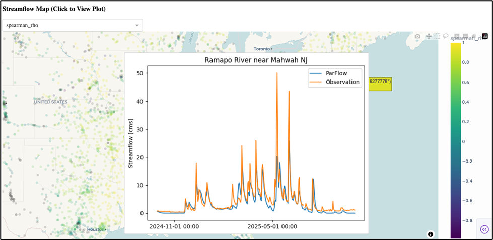
Recently our team, together with collaborators at the University of Arizona, has been building a continental‑scale model of water movement across the entire United States using the integrated groundwater model ParFlow. A model this large produces quite a bit of data, and one of my goals was to make it easier for the research team to explore and interpret the results. To help with this, I built a small interactive dashboard using Dash, a Python framework that lets you create web apps with interactive plots and maps. The dashboard lets us directly compare model results with real‑world observations: for example, streamflow measurements from monitoring stations. This helps researchers quickly see where the model is performing well and where it may need adjustment.

While there were some quirks to get the initial dashboard set up, the step that proved to be more challenging was in how to share it with all of the collaborators.

Our group works on a high‑performance computing (HPC) cluster, because our simulations are too large to run on a laptop. But HPC environments aren’t naturally designed for running web applications, especially not ones that multiple people may want to launch on demand.

We needed a solution that would:

  • Let anyone on the team launch the dashboard without installing software
  • Scale up if we wanted to start visualizing the project’s larger datasets
  • Be friendly to both programmers and non‑programmers

That’s where Open OnDemand came in.

Open OnDemand (OOD) is a web platform that sits on top of an HPC cluster and gives users the ability to run jobs, move files, and launch applications, all from a browser. Instead of everyone needing to memorize Unix commands or write job scripts, they can launch the dashboard in just a couple of clicks.

What I didn’t know at first was that OOD supports two distinct ways of deploying custom applications. Choosing between them turned out to be a key technical decision.

Open OnDemand supports:

1. Passenger Applications

These behave like traditional web apps.

  • They run on the cluster’s login or “head” node.
  • They’re ideal for small, lightweight applications with modest computing needs.
  • They automatically stay online, which is convenient.

For our dashboard, this approach wasn’t ideal. Because our visualizations can involve large model outputs, running everything on the head node could slow things down or interfere with other users.

2. Interactive Applications

These work differently:

  • Each time a user launches the app, OOD submits a job to the cluster
  • That job reserves compute resources on one of the worker nodes
  • OOD then connects the user’s browser to that job so the app runs inside the HPC environment

This design has important advantages:

  • The dashboard can use as much memory or computing power as the user requests
  • Each user gets their own isolated instance
  • It keeps our options flexible in case we want to add more computational complexity to the dashboard in the future

For our use case, we decided the Interactive App approach gave us the most flexibility for future development.

In the final setup, running the dashboard looks like this:

  1. A collaborator logs into our cluster’s Open OnDemand page
  2. They click on the dashboard’s icon under “Interactive Apps”
  3. They choose how many hours their session will be
  4. They click “Launch”
  5. Within a minute or two, a unique dashboard session opens right in their browser

This means hydrologists who may not write code every day can still explore large datasets and investigate model behavior, without ever touching the command line.

Setting this up taught me a lot about how Open OnDemand handles custom applications. To help others who might be trying something similar, I put together a small GitHub repository with several “Hello World” examples to show how both Passenger and Interactive apps can be developed, both with and without Dash.

You can find it here: https://github.com/amy-defnet/hello-world-ood

Making scientific tools accessible is just as important as building them. By turning complex datasets into an interactive dashboard that anyone on the team can launch with a few clicks, we’ve made it easier for researchers to analyze results, spot issues, and ask new scientific questions. I’m excited to continue improving this tool and exploring new ways to help scientists use computational models more effectively.

Posted in Uncategorized

Advent of Code 2025 in Typescript

After two years of Advent of Code in Rust, I thought I’d try TypeScript. I’ve always wanted to improve repo-review’s webapp, and that requires knowledge of the packaging systems for JavaScript, so I thought I’d try TypeScript this year. I also used this as an opportunity to learn more AI tooling too, mostly CoPilot in VSCode & ChatGPT. I’d like to share my experience and thoughts! My code is at aoc2025 (and aoc2024, aoc2023).

Background

Since this is my experience with TypeScript, I should start with my background. I’m very familiar with Python, C++, Rust, and Ruby, and some experience with a few other languages, including JavaScript. I largely interact with JavaScript because I am providing WebAssembly code in the browser, and that’s how you set up the WebApp running Python or whatever. That’s also why I’m interested in how to do that properly; repo-review’s webapp runs in live JSX, and is not properly bundled. Of course, it uses Python, which is several MB, so it isn’t that important to bundle it up, but I’d like to do better eventually.

I’m pretty heavily involved in Python packaging, having written the Scientific Python Library Development Guide and parts of packaging.python.org, and maintain a variety of foundational tools, including packaging, build, scikit-build-core, pybind11, and nox, among others.

As part of the Princeton RSE program, I’ve seen a lot of my colleagues starting to use and talking on AI (also developing it), and I’ve been wanting a chance to do more with it. Several of us also do the Advent of Code each year as a language learning exercise.

Getting started: packaging

In my opinion, “packaging” is the most important software skill. By packaging, I don’t just mean “how to ship code”, I mean how to develop code – the infrastructure you use to run tests, formatters and linters, manage dependencies, etc. I started by asking ChatGPT for what was commonly done, and also did some searching; and settled on pnpm, which was a fast modern alternative to npm (and yarn, etc). AI tends to be really bad at this, by the way; it doesn’t handle changes all that well to the way things are done. Once I had picked a tool, then it produced somewhat useful suggestions on how to set it up, and I also had to consult the documentation a little (but not much). This is approximately the commands I ended up with at first:

brew install pnpm node
pnpm init
pnpm install --save-dev typescript tsk @types/node

Continue reading on ISciNumPy →

Posted in Uncategorized

NeurIPS spotlight: SWE-smith: Scaling Data for Software Engineering Agents

The following work received a spotlight at NeurIPS:

John Yang, Kilian Lieret, Carlos E. Jimenez, Alexander Wettig, Kabir Khandpur, Yanzhe Zhang, Binyuan Hui, Ofir Press, Ludwig Schmidt, Diyi Yang

Despite recent progress in Language Models (LMs) for software engineering, collecting training data remains a significant pain point. Existing datasets are small, with at most 1,000s of training instances from 11 or fewer GitHub repositories. The procedures to curate such datasets are often complex, necessitating hundreds of hours of human labor; companion execution environments also take up several terabytes of storage, severely limiting their scalability and usability. To address this pain point, we introduce SWE-smith, a novel pipeline for generating software engineering training data at scale. Given any Python codebase, SWE-smith constructs a corresponding execution environment, then automatically synthesizes 100s to 1,000s of task instances that break existing test(s) in the codebase. Using SWE-smith, we create a dataset of 50k instances sourced from 128 GitHub repositories, an order of magnitude larger than all previous works. We train SWE-agent-LM-32B, achieving 40.2% Pass@1 resolve rate on the SWE-bench Verified benchmark, state of the art among open source models. We open source SWE-smith (collection procedure, task instances, trajectories, models) to lower the barrier of entry for research in LM systems for automated software engineering. All assets available at swesmith.com.

https://arxiv.org/abs/2504.21798

Posted in Uncategorized